Gas purging procedure
The purging of natural gas (NG) installations with volumes from 0.03 m³ to 1.0 m³ requires a specific procedure.
Purpose
The purpose of this procedure is to assist gasfitters purge natural gas (NG) installations with volumes from 0.03 m³ to 1.0 m³. For installation volumes up to 0.03 m³ refer to AS 5601: 2013, Appendix D Purging.
Purging
Purging is carried out to avoid the possibility of an explosive air/gas mixture existing or forming in consumer piping, appliances or confined spaces.
Purging is defined as the displacement of:
- air, or an inert gas, by a fuel gas
- a fuel gas by air, or an inert gas.
Purging to displace air or inert gas with a combustible gas must take place immediately following a successful gas tightness test.
Nitrogen is the preferred inert gas for purging.
Requirements
The following are requirements of the procedure.
Safety requirements
- Minimise obstructions to reduce the hazards of an untidy workplace.
- Report any leaks or potential hazards.
- Know the location and use of fire extinguishers, fire blankets, fire exits.
- Have adequate ventilation.
- All ignition sources should be controlled or eliminated.
- No naked flames near gas.
Installation volumes from 0.03 m³ to 1.0 m³
- Ensure that the pipe work is gastight, and all open ends are sealed before allowing gas to enter.
- The pressure created during purging should not exceed the design operating pressure and must not exceed the pressure to which the pipe has been tested.
- Pipe work being permanently taken out of service must be isolated physically by removing a section of pipe work or by spading.
- Decommissioned pipe work must be left purged with inert gas.
Process
The process has the following components.
Preparation
Preparation before purging
- An accurate plan of the pipe work system must be available.
- The purging procedure must be planned carefully including the number of persons required to safely carry out the purge.
- No other work on the installation is to take place during the purging operation. Purge points are to be located at the end of the main run and the end of each branch.
- A gas detector capable of measuring all ranges, percentage lower explosive limit (LEL) to 100% gas will be required when purging to gas or from gas to an inert gas. (Minimum 95% gas required for complete purge to gas).
- NG is lighter than air and has a flammability range of between 5% and 14% gas in air.
Site preparation
Do not commence purging until a purge area has been defined, made safe and has been cleared of all ignition sources such as naked flames, pilot lights, and electrical switchgear. Do not allow smoking in or near the purge area and use appropriate signage to indicate this. Inform persons concerned that gas purging will take place.
Enough suitable fire extinguishers should be provided and situated near the venting point. Personnel should be familiar with their use.
Understanding design and location of purging equipment
Purged gas should be vented to the outside atmosphere and away from any buildings, air intakes or electrical ignition sources. To do this, a purge stack or a purge bucket may be required.
Select a location where purged gases will be dispersed quickly and will not give rise to complaints about a smell of gas.
Purging hoses must be suitable for containing the gas, be gastight and properly secured. Hose materials, such as polyethylene, could generate static electricity and must not be used.
Purging the installation
- Calculate the volume of the main run of pipe before commencing the purge. Observing the volume passing through the meter will indicate when gas is expected to flow through the purge stack or the purge bucket.
- Note the meter test dial position.
- Connect the purge stack or the purge bucket to the furthest point on the main run.
- Open the control valves and commence the purge.
- Ensure the maximum purging pressure is not exceeded.
- Continue to purge through the purge stack or purge bucket until natural gas starts to emerge.
- Take a sample from the purge stack or purge bucket sampling point using a suitable gas detector (minimum acceptable reading 95% gas). An indication that the purging of natural gas is nearing completion is seen when a mass of bubbles lift off and float away from the purge bucket.
- Continue purging and testing until an acceptable reading is obtained.
- When the correct test result is obtained, the purge of this section of the installation will be complete.
- Relieve the pressure in the purge hose by opening the purge stack main valve.
- Disconnect the purge hose and the hose inlet valve from the installation, capping off immediately to avoid gas escaping and air re-entering the line.
- Transfer the purge stack or purge bucket and hose to the end of the branch nearest the meter and repeat the procedure.
- Continue purging all branches, moving away from the meter, until the whole installation is filled with gas.
Purging through an appliance
- Turn on one burner until gas is detected.
- Let the gas flow for a few seconds, then turn off and allow time for accumulated gas to disperse.
- Turn on one gas control valve again and apply a continuous burning flame at the burner until the gas is alight and the flame is stable.
- Continue to purge each branch.
Purging through an appliance fitted with a flame safeguard system
- It may be necessary to break the appliance connection until gas is detected. This should be carried out in a controlled manner and with extreme care. The use of a bonding strap is advised.
- When purging to an appliance with the flame safeguard requiring disconnection (from the appliance), care must be taken to prevent an accumulation of natural gas that could lead to an explosive mixture igniting. Purging to outside will ensure hazards are minimised.
- When gas is detected, reconnect the appliance and allow time for any gas to disperse.
- Follow the manufacturer’s lighting instructions until ignition is successful and the appliance is operating satisfactorily.
Replacing air or natural gas with an inert gas (De-commissioning)
Where required, this procedure is suitable for totally displacing all air or natural gas from a gas installation.
Nitrogen is the preferred inert gas for purging.
This procedure must be carried out where:
- Any consumer piping being commissioned has a diameter exceeding those listed in AS 5601:1, Table D2.
- Consumer piping, regardless of length or diameter, is being de-commissioned and a hazard may be created. For example, when welding or cutting into the gas line.
- Consumer piping, regardless of length or diameter and containing a vessel (for example a surge tank), is being commissioned or de-commissioned.
Notes
- When part of the consumer piping is being taken out of service, isolate the gas meter or the section of consumer piping not being purged by means of an effective spade. The nitrogen should be injected at that point.
- Extra care should be taken where pressure vessels are involved. Consider using an appropriate specialist company to assist in planning the purge and to analyse the gas samples.
Calculating the volume of nitrogen required
The procedure for determining the volume of nitrogen gas required for a purge is as follows:
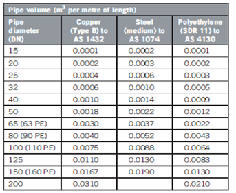
- Determine the volume of pipe in a main run of consumer piping i.e. from the meter to the furthest point and the volume of pipe in each branch.
- Add together all volumes calculated in previous step and multiply by a factor of 1.5. This gives the total volume of nitrogen required to carry out the purge.
- Refer to tables for the appropriate size of nitrogen cylinder required. (An extra cylinder may be ordered as a precaution).
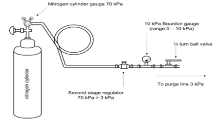
Nitrogen set pressures
The setting pressure of the cylinder regulator is 600 kPa. The second stage regulator is to be set to provide a flowing pressure of 3 kPa with a lock up pressure of approximately 6 kPa. Refer to the diagram below.
Preparation before purging
Ensure that the purging and inert gas equipment is correctly installed and that all valves are closed.
Purging the installation
- Record the reading of the cylinder pressure gauge.
- Slowly open the valve at the outlet of the line pressure gauge.
- Leak test all connections and fittings between the nitrogen cylinder and the consumer piping. Open the valve to purge the hose and check the purge stack connections for leaks.
- Slowly open the main valve on the purge stack. As this valve is opened, the sound of flowing gas should be heard. If desired, a manometer may be connected to the purge stack to determine if gas flow is occurring.
- Continue purging until the required volume of nitrogen has been injected.
- Turn off the main valve on the purge stack.
- Disconnect the purge hose and the hose inlet valve from the installation, capping off immediately to avoid gas escaping and air re-entering the line.
- Transfer the purge stack and hose to the end of the branch nearest the meter and repeat the procedure.
- Continue purging all branches, moving away from the meter, until the whole installation is filled with gas.
Testing for completion of purge
Use the following information to assist with the completion and testing.
Commissioning (air to nitrogen)
Field analysis to prove the completion of an air to nitrogen purge is not practical. It is important to ensure that a sufficient volume of nitrogen has been used for a complete and successful purge.
Testing for completion of purge – De-commissioning (gas to nitrogen)
Gas Sample Test Method: use a suitable gas detector able to read 0.5% gas (10% of LEL) or less to ensure the fuel gas has been eliminated. Note: natural gas has a flammability range between 5% and 14% gas in air.
Tables
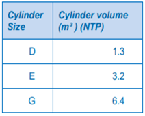
| Cylinder size | Cylinder volume m3 NTP |
| D | 1.3 |
| E | 3.2 |
| G | 6.4 |
Pipe volume (m3 per metre of length)
| Pipe diameter (DN) | Copper (Type B) to AS 1432 | Steel (medium) to AS 1074 | Polyethylene (SDR 11 to AS 4130) |
| 15 | 0.0001 | 0.0002 | 0.0001 |
| 20 | 0.0002 | 0.0003 | 0.0002 |
| 25 | 0.0004 | 0.0006 | 0.0003 |
| 32 | 0.0006 | 0.0010 | 0.0004 |
| 40 | 0.0010 | 0.0014 | 0.0009 |
| 50 | 0.0018 | 0.0022 | 0.0012 |
| 66 (63 PE) | 0.0030 | 0.0037 | 0.0022 |
| 80 (90 PE) | 0.0040 | 0.0052 | 0.0043 |
| 100 (110 PE) | 0.0075 | 0.0088 | 0.0064 |
| 125 | 0.0110 | 0.0130 | 0.0083 |
| 150 (160 PE) | 0.0167 | 0.0190 | 0.0130 |
| 200 | 0.0310 | 0.0210 |
Certificate of compliance
Work Health and Safety Act 2012 (SA)
Work Health and Safety Regulations 2012 (SA)
Managing the work environment and facilities – Code of Practice 2018
Equal Opportunity Act 1984
Environment Protection Act 1993
WHS policies and procedures
Version 1.0 – Last updated 19/2/2022